Table of Contents
Introduction to Electric Current and Its Effects
Electric Current
It is the flow of electricity through a conductor, such as wires and cables. Think of it like water flowing through a pipe.
Importance
Electric current is crucial because it runs a wide range of electrical appliances we use daily, from simple bulbs to complex computers.
Production & Transmission
Electricity is generated at power stations, which can be thought of as ‘electricity factories’. From there, it is transmitted to our homes and schools through networks of thin wires and electric poles, or sometimes via underground cables. This network acts as a delivery system, bringing electricity to where it’s needed.
Also Check- Rapid Revision – Class 7 Science- Chapter 14 – Electric Current and Its Effects
Electric Circuits
Definition
An electric circuit is a continuous path that allows electric current to flow. Imagine it as a track for the electricity to travel along.
Components
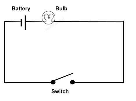
The main components of a simple electric circuit include wires (which act like roads for electricity), a bulb (which shows if electricity is flowing by lighting up), and a switch (which controls the flow of electricity, much like a gate).
Closed vs Open Circuit-
- Closed Circuit- When the switch is in the ON position, the circuit is closed. This means the path for electricity is complete, allowing current to flow and the bulb to light up.
- Open Circuit- Conversely, when the switch is OFF, the circuit is open. In this case, the path is broken, and no electricity flows, so the bulb remains off.
A circuit diagram is used to represent these components and their connections in a simplified way, using symbols for each element (like a map of the circuit). This helps in understanding how everything is connected without drawing the actual components.
When the Bulb Does Not Glow– Even with the switch ON, sometimes the bulb might not light up. This usually happens if the bulb is fused, meaning its filament (a thin wire inside the bulb) has broken. This break interrupts the flow of electricity, much like a bridge being out stops traffic on a road.
Also Check- Chapter 10 – Electric Current and its Effects – 5 Worksheets Solved and Unsolved
Circuit Diagram
Purpose
A circuit diagram is like a blueprint for an electric circuit. It visually represents how various components, like cells, batteries, switches, and bulbs, are connected in an electric circuit using specific symbols. This makes it easier to understand and build circuits without physically constructing them.
- When the Bulb Glows- In a circuit diagram, when the switch is represented as closed (in the ON position), it indicates that the electric circuit is complete, allowing current to flow and the bulb to light up.
- When the Bulb Does Not Glow- Sometimes the bulb may not light up even if the switch is in the ON position. In a circuit diagram, this can be represented by a broken or incomplete connection, often indicating that the bulb is fused or its filament is broken.
- Simplification- Drawing actual electric components can be complex and time-consuming. Therefore, circuit diagrams use simplified symbols for each component, making it easier to draw and interpret.
Electronic Components and their Symbols
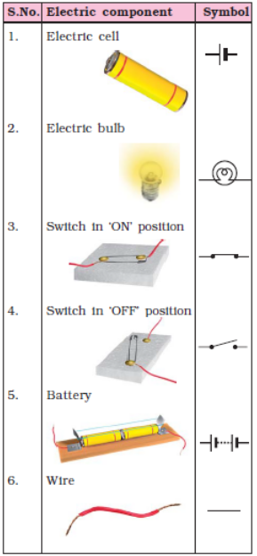
Definition
Electronic components are the basic elements that make up an electric circuit and contribute to its functioning.
Common Symbols
These symbols are standardised representations of various electronic components. Examples include-
- Cell/Battery- Represented by one or more parallel lines, indicating positive and negative terminals.
- Switch- Shown as a break or gap in a line, which can be closed (ON) or open (OFF).
- Bulb/Light- Often represented by a circle with a cross or a loop inside.
Importance of Symbols
These symbols provide a universal language for understanding and designing electrical circuits. They are used worldwide and help in creating a clear and concise representation of how a circuit functions.
Electric Cell and Battery
Electric Cell
It is a basic source of electricity commonly used in various devices like torches, radios, electric clocks, watches, and toys. A single electric cell typically provides around 1.5 volts of electricity. This is much lower than the electricity supplied from power stations to our homes, which is usually around 220 volts.
Battery
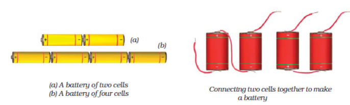
A battery is made up of multiple electric cells. It is used when a single cell’s voltage is insufficient for a device. Batteries can be single-use or rechargeable. For example, car batteries are made of cells that can be recharged, whereas ordinary cells in smaller devices usually cannot be.
Also Check- Batteries- The Powerhouses of Everyday Life – A Guide for Upper Primary Students
Combination of Electric Cells- Series vs Parallel
Series Connection-
- How It Works- Cells are connected in series when the positive terminal of one cell is connected to the negative terminal of another.
- Result- This increases the overall voltage. For instance, in a torch, the cells are placed one after another in series.
- Voltage Addition- If each cell provides 1.5 volts, connecting two cells in series would result in a total voltage of 3 volts.
Parallel Connection-
- How It Works- In parallel connection, cells are placed side by side. This means the positive terminals of all cells are connected together, and the same goes for the negative terminals.
- Usage- This type of connection is common in devices like TV remote controls.
- Effect- Connecting cells in parallel increases the capacity (duration for which they can provide power) but the voltage remains the same as a single cell.
Important Note- Connecting the positive terminal of one cell to the positive of another, and the same with the negative terminals, does not work. This setup does not create a functional battery.
Effects of Electric Current- Heating Effect
Heating Effect
When electric current passes through a device, it can produce heat. This is known as the heating effect of electric current. For example, when you turn on an electric heater or bulb, the elements inside become red hot and release heat, which is a direct result of this heating effect.
Factors Affecting the Heating Effect-
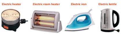
- Resistance of the Wire- The resistance of a wire significantly influences the heating effect. Higher resistance in the wire means more heat will be produced. For instance, if you pass the same amount of current through a copper wire and a nichrome wire of the same length and thickness, the nichrome wire will become hotter than the copper wire. This is because nichrome has a higher resistance than copper. That’s why nichrome is used in heating elements like electric room heaters and irons.
- Magnitude of Current- The amount of current flowing through the wire also affects the heat generated. A higher current will produce more heat. In household wiring, if a large current accidentally flows through the wires, they can become extremely hot and potentially start a fire.
Applications of the Heating Effect of Current
The heating effect of electric current is not just a theory; it has practical applications in everyday life-
- Electric Bulbs- The filament inside an electric bulb heats up due to the electric current, producing light. This is a direct application of the heating effect.
- Electrical Heating Appliances- Appliances like water heaters, room heaters, and electric irons utilise the heating effect. When they are switched on, the electric current heats up their elements, allowing them to perform their functions.
- Electric Fuse- A very crucial application is in electric fuses, which are safety devices. Fuses contain a wire that heats up and melts if too much current flows through it, breaking the circuit and preventing potential hazards like fire or damage to appliances.
Magnetic Effect of Electric Current
Discovery
The magnetic effect of electric current was discovered by Hans Christian Oersted. He observed that when an electric current passes through a wire, it causes a nearby compass needle to deflect from its usual North-South position. This was a groundbreaking discovery as it linked electricity and magnetism, which were previously thought to be unrelated.
Principle
A wire carrying electric current behaves like a magnet. This is the basic principle behind the magnetic effect of current.
- Straight Wire- When current flows through a straight wire, it produces a magnetic effect around the wire.
- Enhanced Effect with Coils- This magnetic effect is increased if the wire is coiled. More turns in the coil mean a stronger magnetic effect.
- Further Enhancement with Iron Core- The magnetic effect is further increased if the coil is wound around an iron rod, and then current is passed through it. The iron core amplifies the magnetic field produced by the coil.
Lightning and Magnetism
Lightning
It is a natural phenomenon that occurs during thunderstorms, involving a spectacular display of electric discharge.
- Process- Air currents move upwards and water droplets move downwards in a storm, creating a separation of charges between clouds and between clouds and the Earth. As the charge buildup increases, air, which is normally a poor conductor of electricity, starts conducting electricity.
- Manifestation– This flow of charge, known as lightning, is accompanied by bright streaks of light and sound.
Creation of Natural Magnets
Interestingly, lightning also plays a role in creating natural magnets, known as lodestones. These are pieces of naturally magnetised mineral magnetite, and their magnetic properties are believed to be the result of lightning strikes.
Electric Bulb and Electric Fuse
Electric Bulb-
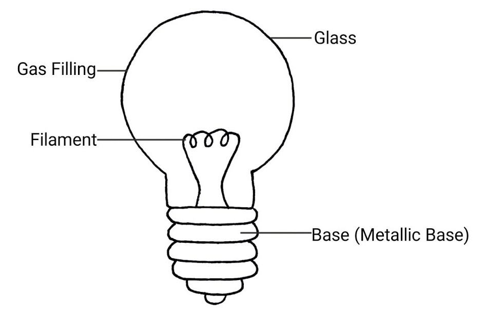
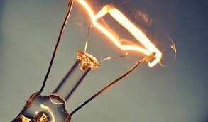
- How It Works- The electric bulb works based on the heating effect of electric current. Inside the bulb, there is a coil of wire known as the filament.
- Filament Heating- When electric current passes through this filament, it gets extremely hot and starts to glow, producing light.
- Design- This glowing of the filament due to the heating effect is the principle behind the illumination provided by the bulb.
Electric Fuse-
- Purpose- A fuse is a safety device used to prevent excessive current flow in electrical circuits.
- Material and Function- Fuses are made of a material that melts easily. When too much current flows through the circuit, the fuse wire melts, breaking the circuit. This interruption in the circuit flow prevents potential hazards like fire or damage to the electrical system.
- Significance- Fuses are critical for maintaining safety in electrical systems, especially in situations of overloading where the risk of fire or circuit damage is high.
Compact Fluorescent Lamps (CFLs)
Advantages-
- Energy Efficiency- CFLs are more energy-efficient compared to regular incandescent bulbs.
- Less Heat, More Light- Unlike traditional bulbs, which waste a significant portion of electricity in heat, CFLs convert more electricity into light. This results in less energy wastage.
- Design and Function- CFLs do not have a filament like regular bulbs. Instead, they contain a gas that produces ultraviolet light when electric current passes through it. This ultraviolet light then interacts with the fluorescent coating inside the bulb to produce visible light.
- Considerations- When purchasing CFLs or other bulbs, it’s recommended to look for the ISI mark (Indian Standards Institute). This mark ensures that the appliance meets certain safety and energy efficiency standards, ensuring minimal wastage of electricity.
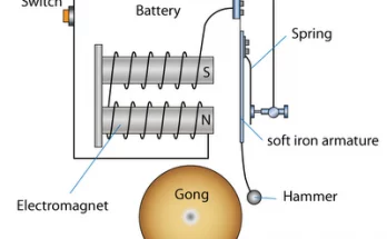
Electric Bell- Components & Working
Construction
An electric bell typically consists of a U-shaped electromagnet. Attached to this electromagnet is a small iron bar called an armature. This armature is connected to a clapper at one end and a flat spring at the other. Near the clapper, there is a metal gong.
Working Principle-
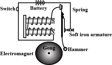
- Magnetization- When the bell’s switch is pressed, it completes the electric circuit, allowing current to flow through the electromagnet’s coil. This magnetises the electromagnet.
- Attraction and Sound Production- The magnetised electromagnet then attracts the iron armature towards itself, causing the clapper to strike the gong and produce a ringing sound.
- Break in Circuit- As the armature moves towards the electromagnet, it breaks contact with a contact screw, interrupting the circuit. This loss of contact causes the electromagnet to lose its magnetism momentarily.
- Reset- The flat spring pulls the armature back to its original position, which restores contact and completes the circuit again, allowing the process to repeat.
- Continuous Ringing- As long as the switch is pressed, this process of making and breaking the circuit continues, causing the armature to rapidly vibrate and the clapper to repeatedly strike the gong, producing a continuous ringing sound.
Also Check- Electromagnets- A Guide for Upper Primary Students
Electromagnets
Definition
An electromagnet is a type of magnet where the magnetic field is produced by an electric current. It consists of a coil of insulated wire wrapped around an iron core, which becomes magnetised only when electric current passes through the coil.
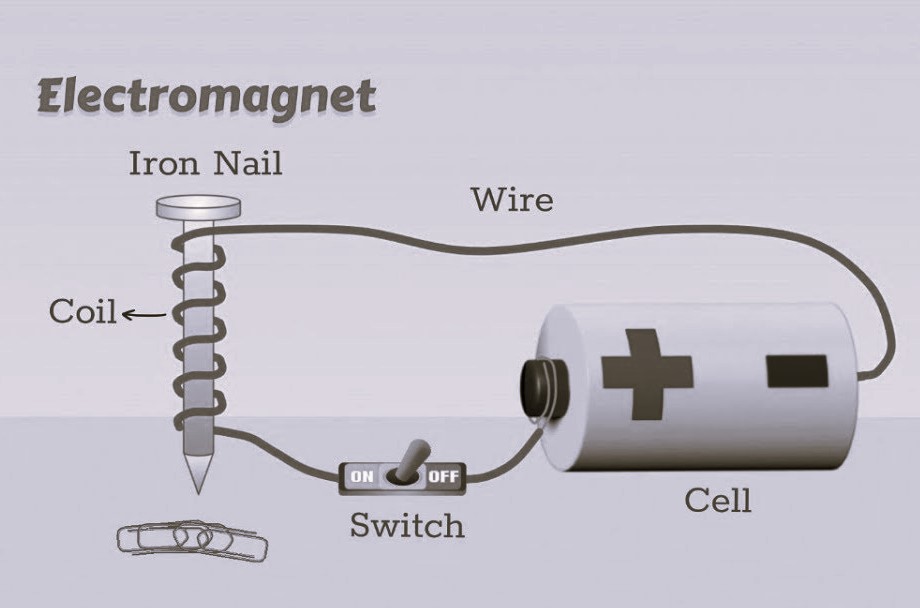
Advantages over Permanent Magnets-
- Control Over Magnetism- The magnetism of an electromagnet can be easily turned on or off by controlling the electric current. This is not possible with permanent magnets.
- Adjustable Strength- The strength of an electromagnet can be adjusted by changing the amount of current flowing through the coil or by increasing the number of turns in the coil. This allows electromagnets to be much stronger than permanent magnets.
Uses
Electromagnets are widely used in various devices like electric bells, motors, and other electrical appliances due to these versatile properties.
Safety and Hazards
Hazards- The main electrical hazards in household wiring are overloading and short circuits.
- Overloading- This occurs when too many electrical appliances are connected to a single socket, drawing a large amount of current. Overloading can heat the wires to very high temperatures, potentially causing fires.
- Short Circuit- A short circuit happens when the insulation of live and neutral wires wears out, and they come into direct contact. This causes a large current to flow through the wiring, heating the wires dangerously and potentially starting a fire.
Safety Devices-
Fuses
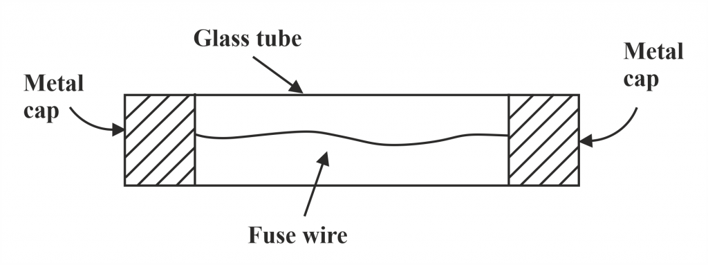
A fuse is a safety device that works on the heating effect of electric current. It consists of a thin wire with a low melting point. If the current increases too much, the wire heats up, melts, and breaks the circuit, stopping the flow of current and preventing potential fires and appliance damage. It’s important not to use a thick wire as a fuse replacement, as it won’t melt appropriately and may not protect the circuit.
Miniature Circuit Breakers (MCBs)
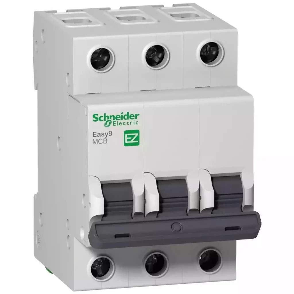
Function- MCBs are modern safety devices increasingly used instead of fuses. Unlike fuses, which work on the heating effect of current, MCBs operate on the magnetic effect of current. They automatically turn off when the current in a circuit exceeds a safe limit, and can be turned back on once the issue is resolved, making them more convenient and reusable compared to fuses.
ISI Mark
Meaning- ISI stands for Indian Standards Institute. The ISI mark on an electrical appliance indicates that it conforms to the safety and quality standards set by the Institute.
- Importance- If an appliance does not have an ISI mark, it means it does not meet the ISI standards and may not be safe to use. Conversely, appliances with the ISI mark are considered safe, of good quality, and efficient in terms of electricity usage. This mark is an important factor to consider when purchasing electrical appliances.
Also Check- Electric Bell Diagram for Class 7 Science
Also Check- Chapter 14- Electric Current and Its Effects-Class 7 science- Question and Answers
Also Check- Chapter 14- Electric Current and Its Effects–Class 7 science- Question and Answer -(Solved MCQs)
Also Check- NCERT Exemplar Solutions- Class 7 Science- Chapter 14 – Electric Current and Its Effects
Also Check- NCERT Solutions for Class 7 Science Chapter 14- Electric Current and its Effects
Also Check- Class 7 science -Chapter 14 – Electric Current and Its Effects- Complete Notes