Table of Contents
Activity 1. Experimenting with the Direction of Current and its Effect on the Deflection of a Compass Needle
Objective- The purpose of this activity is to explore how changing the direction of electric current in a wire affects the magnetic field around it, as evidenced by the movement of a compass needle.
Key Concept-
- Magnetic Field- Electric current flowing through a wire produces a magnetic field around the wire. This field can influence objects that are sensitive to magnetism, like a compass needle. If we change the direction of the current, the direction of this magnetic field also changes.
Materials Needed-
- An electric cell (battery)
- Insulated wires
- A small compass
- A switch
Activity Steps-
Setting Up the Circuit-
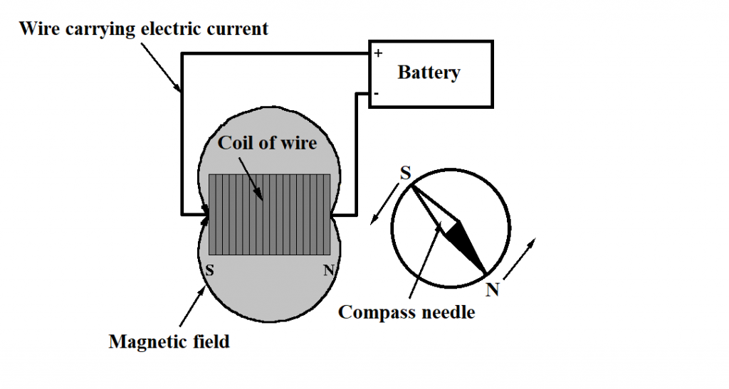
- Create a simple circuit- Connect a wire from the positive terminal of the cell to the switch, then another wire from the switch to one end of a straight piece of wire. Connect the other end of this straight wire back to the negative terminal of the cell.
- Place the compass close to this straight piece of wire so that the compass needle is parallel to it.
Observing the Compass Needle-
- With the switch in the ‘OFF’ position, observe the initial position of the compass needle.
- Now turn the switch to the ‘ON’ position, allowing current to flow through the wire.
- Observe the direction in which the compass needle deflects.
Reversing Current Direction-
- Turn off the switch and reverse the connections at the cell’s terminals. This means connecting the wire from the switch to the negative terminal and the return wire to the positive terminal.
- Turn the switch back to the ‘ON’ position and observe the compass needle again.
Recording and Discussing Observations-
- Note the direction of the needle’s deflection in both cases.
- Discuss how the change in the direction of the current affected the deflection of the compass needle.
Understanding the Concept-
- The direction in which the compass needle deflects indicates the direction of the magnetic field created by the current.
- When the current’s direction is reversed, the magnetic field’s direction also reverses, which is observed by the change in the needle’s deflection.
- This activity helps in understanding the relationship between electricity and magnetism, showing that electric currents generate magnetic fields whose direction depends on the current’s direction.
Conclusion-
By experimenting with the direction of electric current and observing its effect on a compass needle, students can visually grasp the concept of electromagnetism. This simple yet effective demonstration highlights the fundamental principles of how electric currents can influence magnetic fields, a key concept in the study of physics and electromagnetism.
2. Making Electromagnets with Different Numbers of Turns to Compare Their Strengths
Objective- This experiment aims to demonstrate how the number of turns in the coil of an electromagnet affects its magnetic strength.
Fundamental Concept-
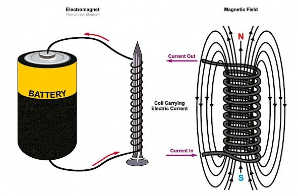
- Electromagnet Strength- The power of an electromagnet is directly influenced by the number of turns or coils of wire wrapped around its core. Generally, the more turns there are, the stronger the magnetic field created by the electromagnet.
Also Check- Electromagnets- A Guide for Upper Primary Students
Materials Required-
- Insulated copper wire (for making coils)
- Iron nails (of the same size)
- An electric cell or battery
- A switch
- Small metal objects like pins or paper clips
- A ruler or measuring tape (for precise measurement of wire)
Steps of the Activity-
Building the Electromagnets-
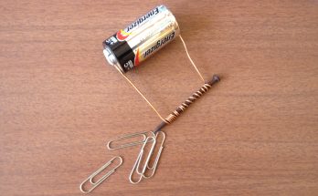
- Create electromagnets by wrapping insulated copper wire around iron nails. Make several electromagnets with different numbers of turns, such as 20, 40, 60, and 80. Ensure that the wire is tightly wound and the turns are close together.
- Strip the ends of the wires for making connections to the battery.
Connecting the Electromagnets-
- Connect each electromagnet to the battery using the switch. Do this one at a time to test each electromagnet individually.
Testing Magnetic Strength-
- Place a box of pins or paper clips near each electromagnet when it is connected to the battery.
- Observe and count how many pins are attracted and held by each electromagnet.
- Record the number of pins attracted for each different coil turn number.
Comparing the Results-
- Analyse the data by comparing the number of pins attracted by each electromagnet.
- Discuss how the number of turns affects the strength of the electromagnet.
Understanding the Concept-
- As the number of turns in the electromagnet increases, the magnetic field around the nail becomes stronger, allowing it to attract more pins.
- This experiment illustrates a fundamental principle of electromagnetism- the magnetic field’s strength is related to the coil’s number of turns and the current flowing through it.
Conclusion-
This activity provides a hands-on experience for students to understand how an electromagnet’s strength can be varied. By observing the different effects of each electromagnet on the pins, students can visually grasp the relationship between the number of coil turns and the strength of the magnetic field. This foundational understanding is crucial in learning about electromagnetism and its applications in various fields.
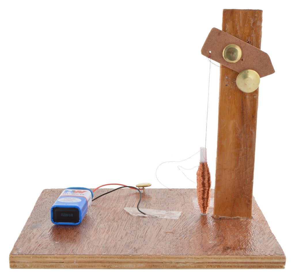
3. Creating a Working Model of a Railway Signal Using an Electromagnet
Objective- The goal of this project is to create a working model of a railway signal using an electromagnet to demonstrate how electromagnetism can be used to produce motion in mechanical systems.
Key Concept-
- Electromagnetism in Motion- Electromagnets, when activated, create a magnetic field strong enough to move objects. This principle is widely used in various mechanical systems, including railway signals.
Materials Needed-
- An iron nail (about 6–10 cm long)
- Insulated copper wire
- A small cardboard piece (to act as the signal arm)
- An electric cell or battery
- A switch
- Glue or tape
- Additional materials for support and decoration (like a small wooden block or plasticine)
Steps of the Activity-
Building the Electromagnet-
- Wind the insulated copper wire tightly around the iron nail to create an electromagnet. Make sure to leave free ends of the wire for connection.
- Strip the ends of the wire for making connections.
Assembling the Signal Model-
- Attach the signal arm (cardboard piece) to one end of the electromagnet (nail) using glue or tape. Ensure that the arm can move freely.
- Mount the electromagnet on a support like a wooden block, so it stands upright.
- Optionally, decorate the model to resemble a railway signal.
Wiring the Electromagnet-
- Connect the electromagnet to the electric cell or battery using the switch. This allows you to control the current flowing through the electromagnet.
Operating the Model Railway Signal-
- With the switch in the ‘OFF’ position, the signal arm should be in its default position.
- Turn the switch to the ‘ON’ position. The electromagnet will become magnetised and pull the signal arm, indicating a change in position.
- Turn the switch ‘OFF’, and the signal arm should return to its original position.
Understanding the Concept-
- The electromagnet, when activated, creates a magnetic field that can exert force on nearby objects, in this case, the signal arm.
- The model demonstrates how electromagnets can be used to create controlled movement, an essential function in mechanical and electrical systems, such as railway signals.
Conclusion-
This project helps students understand the practical application of electromagnets in mechanical systems. By building a model railway signal, they can visually grasp how electromagnets can be used to control movement, a fundamental concept in many modern technologies. The activity also encourages creativity and problem-solving, as students figure out how to effectively construct and operate the model.
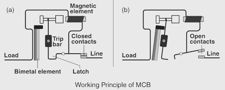
4. Visiting an Electric Shop to Learn About Various Types of Fuses and Miniature Circuit Breakers (MCBs)
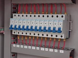
Objective- This activity aims to provide students with hands-on, practical knowledge about fuses and MCBs, their functions, and their critical roles in maintaining electrical safety.
Key Concept-
- Electrical Safety Devices- Fuses and MCBs are crucial components in electrical circuits designed to protect against damage due to excess current. They act as safeguards by interrupting the flow of current in events like overloads or short circuits.
Preparation for the Visit-
- Research basic information about fuses and MCBs to have foundational knowledge.
- Prepare a list of questions or topics to discuss with the electrician.
Steps of the Activity-
Planning the Visit-
- Arrange a visit to a local electric shop or a hardware store where electrical components are sold.
- Ensure the visit is supervised by an adult, preferably with some knowledge of electrical systems.
Interaction with the Electrician-
- Request the electrician or shopkeeper to show you different types of fuses and MCBs.
- Observe the physical differences between various fuses and MCBs.
Learning about Their Functions-
- Ask the electrician to explain how each type of fuse and MCB works.
- Understand the conditions under which these devices operate, such as how they detect overload or a short circuit.
Understanding Their Importance-
- Discuss the role of fuses and MCBs in household and industrial electrical systems.
- Learn about the consequences of not having these safety devices in place.
Comparing Fuses and MCBs-
- Learn the differences between fuses and MCBs, such as how MCBs can be reset while fuses need to be replaced after they ‘blow’.
- Understand the scenarios in which one might be preferred over the other.
Conclusion-
This visit provides an opportunity for students to connect theoretical knowledge with real-world applications. By interacting with professionals and observing various types of fuses and MCBs, students gain a deeper understanding of these essential safety devices. They learn how fuses and MCBs function to prevent electrical accidents, highlighting the importance of electrical safety in everyday life. This experience can also spark interest in further exploration of electrical engineering and technology.
Also Check – Chapter 10: A Detailed Guide to “Electric Current and its Effects” Activities for Class 7 Students
Also Check- Chapter 10 – Electric Current and its Effects – 5 Worksheets Solved and Unsolved
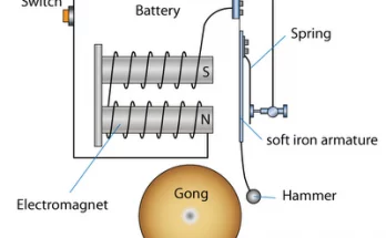
Also Check- Electric Bell Diagram for Class 7 Science
Also Check- Rapid Revision – Class 7 Science- Chapter 14 – Electric Current and Its Effects
Also Check- Chapter 14- Electric Current and Its Effects-Class 7 science- Question and Answers
Also Check- Chapter 14- Electric Current and Its Effects–Class 7 science- Question and Answer -(Solved MCQs)
Also Check- NCERT Exemplar Solutions- Class 7 Science- Chapter 14 – Electric Current and Its Effects
Also Check- NCERT Solutions for Class 7 Science Chapter 14- Electric Current and its Effects
Also Check- Class 7 science -Chapter 14 – Electric Current and Its Effects- Complete Notes
Also Check – Electric Bell Working Mechanism Simplified for Students
Also Check- Batteries- The Powerhouses of Everyday Life – A Guide for Upper Primary Students